> ## Documentation Index
> Fetch the complete documentation index at: https://docs.flexwash.com/llms.txt
> Use this file to discover all available pages before exploring further.
# Elka Gates
> Specific config for gate queue stacking.
The advice provided here is just advice that we think may help. These gates are high voltage machines and you should always check with a license electrician or contact the manufacturer first. FlexWash assumes no liability for any injury financial or otherwise.
## Installation
### Register Config
All Gates\
These registers need to be set for every gate.
| | Register | Value |
| :--------------------- | :------- | :--------------------------------------------------------------------------------------------- |
| Gateway | P220 | 172 |
| | P221 | 162 |
| | P222 | 184 |
| | P223 | 1 |
| Subnet Mask | P230 | 255 |
| | P231 | 255 |
| | P232 | 255 |
| | P233 | 0 |
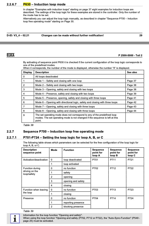
| Number of Safety Loops | P630 | Typically 1, but can be more if they have more safety loops. See section below on Safety Loops |
| Safety Loop | P701 | 1 |
| | P702 | 1 |
| | P703 | 1 |
| | P704 | 0 |
Gate 1
| | Register | Value |
| :--------- | :------- | :---- |
| IP Address | P210 | 172 |
| | P211 | 162 |
| | P212 | 184 |
| | P213 | 4 |
Gate 2
| | Register | Value |
| :--------- | :------- | :---- |
| IP Address | P210 | 172 |
| | P211 | 162 |
| | P212 | 184 |
| | P213 | 5 |
Gate 3 (If you have 3 lanes)
| | Register | Value |
| :--------- | :------- | :---- |
| IP Address | P210 | 172 |
| | P211 | 162 |
| | P212 | 184 |
| | P213 | 6 |
Merge Loop (Optional)\
If you have a gate with a merge loop.
| | Register | Value |
| :--------- | :------- | :---- |
| IP Address | P711 | 1 |
| | P712 | 0 |
| | P713 | 0 |
| | P714 | 0 |
### Verify IP Settings
Confirm the registers above took effect before leaving the site. This test uses a laptop connected directly to the gate, so it isolates the gate's network configuration from the rest of the site's network.
Run a patch cable from the laptop to the gate's ethernet port.
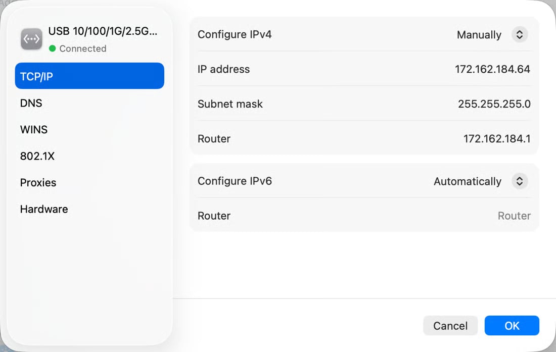
Set the laptop's ethernet interface to configure IPv4 manually. Use an address on the same subnet as the gate but different from every gate on site. We use `172.162.184.64` for this purpose. Set the subnet mask to `255.255.255.0` and the router to `172.162.184.1` to match registers P230 to P233 and P220 to P223.
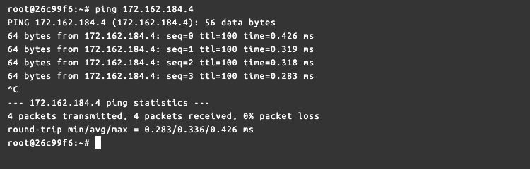
Ping the gate at `172.162.184.x`, where `x` is 4, 5, or 6 depending on the value you saved in register P213. Let the test run for a few seconds, then stop it.
```bash theme={null}
ping 172.162.184.4
```
You should see replies from the gate and 0% packet loss:
If the gate does not reply, go back and verify each register value. If the registers are correct and the gate still does not respond, we recommend contacting [Q-SAQ](https://q-saq.com/) directly for more involved hardware assistance.
## Manufacturer Settings
You can see more information about from the manufacturer's manual.
## Troubleshooting Errors
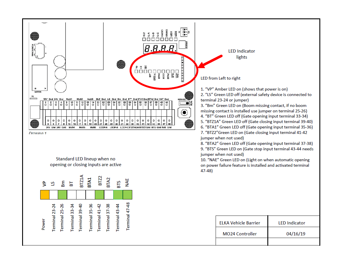
If the gate is misbehaving check these indicator lights, they will fire if there is a mechanical fault.
## Power Cycle the gate
1. Unlock the gate and remove the side panel.
2. Flip the breaker to turn the gate off.
3. Flip the breaker again to turn the gate back on.
## Program the Gate
These instructions are here to help but we recommend using a licensed electrician and consulting with the gate manufacturer before attempting any changes.
1. Press and hold the joystick until the screen shows "P100".
2. Move the joystick up until the screen shows "P200".
3. Press the joystick.
4. Move the joystick up until the screen shows "P210".
5. Press the joystick again.
6. Move the joystick up or down, depending on the number on the screen, until it shows "172".
7. Press the joystick again to save the change.
8. The screen will now show "211". Press the joystick to modify that field.
9. Move the joystick up or down until it shows "162".
10. Again press the joystick to save the change.
11. Repeat the same steps for "212" until "184" shows on the screen and save the change.
12. Repeat the same steps for "213", but the number you will save here will vary depending on the gate you are programming. Gate one will have "4", gate two "5", gate three "6", and so on. Save the change once you set the correct number.
## Gate's arm stuck in open position after power outage
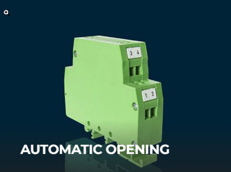
These gates come with a "Automatic Opening" module that might get activated after a power outage or power surge. This module will open the gate and it will remain in the open position. You will know if the module has been activated because the LED screen will display "P.OFF".
To get the gate's arm down and working again normally, the power source will have to be changed on the settings.
1. Press and hold the little joystick circled in the image above for a couple of seconds until the LED screen shows "P100".
2. Press the joystick again.
3. Move the joystick up until the screen shows "P103". Then press the joystick.
4. Move the joystick down or up until the number "0" appears. Then press the joystick one last time to save the change.
If this happens to your gate, the Automatic Opening module needs to be replaced in order for it to open again in another power surge or power outage. Please contact Customer Support if you need a replacement.
 ## Troubleshooting Errors
If the gate is misbehaving check these indicator lights, they will fire if there is a mechanical fault.
## Troubleshooting Errors
If the gate is misbehaving check these indicator lights, they will fire if there is a mechanical fault.
 ## Power Cycle the gate
1. Unlock the gate and remove the side panel.
2. Flip the breaker to turn the gate off.
3. Flip the breaker again to turn the gate back on.
## Program the Gate
## Power Cycle the gate
1. Unlock the gate and remove the side panel.
2. Flip the breaker to turn the gate off.
3. Flip the breaker again to turn the gate back on.
## Program the Gate
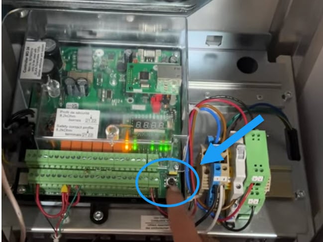 To get the gate's arm down and working again normally, the power source will have to be changed on the settings.
1. Press and hold the little joystick circled in the image above for a couple of seconds until the LED screen shows "P100".
2. Press the joystick again.
3. Move the joystick up until the screen shows "P103". Then press the joystick.
4. Move the joystick down or up until the number "0" appears. Then press the joystick one last time to save the change.
To get the gate's arm down and working again normally, the power source will have to be changed on the settings.
1. Press and hold the little joystick circled in the image above for a couple of seconds until the LED screen shows "P100".
2. Press the joystick again.
3. Move the joystick up until the screen shows "P103". Then press the joystick.
4. Move the joystick down or up until the number "0" appears. Then press the joystick one last time to save the change.